Model Behavior
In the age of computer design, why do engineers still send airplane models to the wind tunnel?
/https://tf-cmsv2-smithsonianmag-media.s3.amazonaws.com/filer/Wind_Tunnel_631-mar07.jpg)
A dust-colored Dodge Dart station wagon races down a narrow road in the Mojave Desert, north of Los Angeles. Six feet above the windshield is a model airplane that looks as if it’s flying backward. Inside the car, the driver maintains speed by reference to a primitive air pressure meter suction-cupped to the windshield; another man, his bushy sideburns fluttering in the hot breeze, flies the airplane with a radio-control modeler’s control box and notes the voltages from crude force gauges aboard the model.
It’s 1975. The man in the right seat is Burt Rutan, the model airplane is the VariEze, and the rig on the roof is his “car-top wind tunnel.” In the years to come, the VariEze will revolutionize airplane homebuilding and Rutan will become the enfant terrible of a generation of aeronautical engineers, masterminding the first private manned flight into space.
Rutan tested that model, and others since then, to validate the novel configurations that are his trademark. Immersing physical models in genuine wind has always been the most direct way to collect aerodynamic information and verify new insights. German aviation pioneer Otto Lilienthal and the Wright brothers conducted hundreds of model tests. Even the great engineer Gustave Eiffel, of Eiffel Tower fame, built large wind tunnels to test wings and whole airplanes well before the start of World War I. Only by viewing and measuring the behavior of scale models in wind tunnels, and by using various tricks to reveal precisely what the air was doing, could aerodynamicists find their way to the best designs. The thick airfoils that made cantilever wings possible, the National Advisory Committee for Aeronautics cowlings that reduced the drag of radial engines, the fillets and fairings that doubled cruising speeds during the 1920s—all came from wind tunnel testing of models and full-scale airplanes.
Gerald Landry, who managed the California Institute of Technology’s famous GALCIT tunnel—Guggenheim Aeronautical Laboratories, California Institute of Technology—until its demolition in 1997, recalls the interactive approach to tunnel testing used by manufacturers like Northrop, Lockheed, and Douglas, which would contract with Caltech for tunnel time. “They would send a whole team, not just aerodynamics guys but the engineering and model shop guys too,” Landry says. “We’d run a test, and if there was a bad area somewhere, the shop guys would take material away or build it up and we’d run it again. I have my thumbprint in a number of airplanes’ wing root fairings.”
This was the procedure when the wing root and landing gear fairings of the six-passenger Northrop Alpha, an early TWA airliner and GALCIT’s first customer, were developed by trial and error in 1931. The Alpha was a triumph of empirical aerodynamics; the drag of the wing-fuselage combination was eventually reduced by half. The original wind tunnel model still exists; it is on display at the Western Museum of Flight in Torrance, California. But it is the exception. Countless of these statues of airplanes-to-be, although prized by collectors as works of art, were discarded or destroyed once they had yielded the necessary information.
Vast quantities of information emerged from decades of wind tunnels tests, filling libraries with reports on everything from the behavior of overall aircraft configurations to the tiniest details of structure or shape. The information found its way into multi-volume compilations of mathematical methods to predict the performance and behavior of new designs. But these methods were like systems to predict weather based on general observations of past trends, rather than on precisely extrapolating from present conditions in light of the basic laws of heat and fluid motion. As with weather forecasting, aerodynamics confronted a problem of sheer scale: The underlying physical laws had been known for a long time, but applying them to practical problems involved staggering numbers of calculations.
The advent of the fast digital computer made it possible to perform these calculations in a reasonable amount of time. Since the 1970s, computational fluid dynamics or CFD—the solution of aerodynamic problems by numerical simulation—has increasingly challenged the wind tunnel for the role of the airplane or missile designer’s most valued tool. Just as the proliferation of office computers inspired predictions of the disappearance of paper, the advent of CFD was claimed to herald the demise of wind tunnels. Both forecasts were premature. Wind tunnel testing still thrives, in part because it provides the indispensable final validation of computed results, and in part because for many kinds of tests it is actually cheaper and faster to build a physical model and test it than it is to prepare a complex and detailed computer model and then analyze it repeatedly over a wide range of flight conditions.
CFD has been, in a way, a perennial victim of its own successes. It is now called upon to solve problems that would have been considered impossible a decade ago. But the persistent obstacle for computer aerodynamics, according to Caltech aerodynamicist Mory Gharib, is the difference in size between the largest and the smallest objects it must deal with.
“Ideally, you would like to be able to analyze the smallest eddies in the flow, the so-called Kolmogorov eddies,” he explains. “But they’re very tiny. To examine the flow field surrounding a full-scale transport on this scale, you’d be calculating for years. So you have to be satisfied with looking at larger chunks, and that leaves you with some uncertainty. That’s where the wind tunnel comes in. It anchors your computational results.”
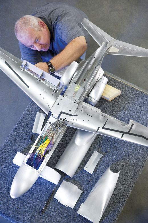
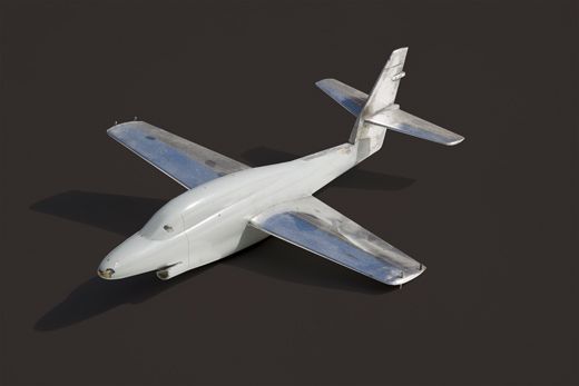
Cost, however, is a persistent issue. Engineers at Honda, enjoying an ample budget for development of a light jet, relied on a continual alternation of computational and wind tunnel results, obtained with a number of different models and in several different tunnels. They arrived at a design that is unconventional—the engines are mounted on pylons that sprout from the upper surface of the wing and the nose bulges strangely—but is claimed to be more efficient than the usual arrangement, in which the engines are attached alongside the rear fuselage. Sino Swearingen Aircraft Corporation, on the other hand, with a tighter budget for developing its own small twin-jet, bypassed wind tunnel testing of the wing, only to lose a prototype and its pilot in flight testing when an unanticipated transonic shock wave made the airplane uncontrollable in roll. Belated wind tunnel testing revealed the problem and provided the fix.
The uncertainty inherent in CFD has given rise to a derisive nickname in the wind tunnel world: Can’t F—-in’ Decide. In reality, however, CFD and wind tunnel testing work synergistically. Designs are first developed and refined computationally, then tested in a wind tunnel to verify the results. Anomalies identified in the wind tunnel are studied with CFD, which is able to resolve fluid behavior more precisely and clearly than tunnel testing can. The wind tunnel tells you that the drag is high; the computer shows you why. The cycle may be repeated many times before the final design crystallizes. But the imponderable element of customer confidence always favors the empirical result. “No one,” says Chris Athaide of Tri-Models, a southern California wind tunnel model fabricator, “will buy an airplane that hasn’t been in a wind tunnel.” John Roncz, a freelance analyst who has contributed to many of Rutan’s designs, makes a similar observation, but from a more cynical—and CFD-oriented—point of view: “The purpose of a wind tunnel test is to convince management to proceed with the program.”
Many models have moving parts, like landing flaps or control surfaces articulated on tiny, geometrically accurate hinges. The quality and precision of their surfaces and joints are breathtaking. But not all models are the beautiful “high fidelity” objects made by the specialty shops. A Revell kit may serve just as well. And although photographs often show models in tunnels being groomed by technicians in white lab coats, real wind tunnels are sloppy places where jeans-clad workers tend scuffed models patched with Bondo and sweep up chips and filing debris between tests. Much wind tunnel work today involves reducing the drag on trucks, automobiles, railroad cars, and even sports gear like golf balls. At NASA’s Ames Research Center in California, a team led by Rabi Mehta has used relatively crude models of trucks and coal cars to find ways of reducing their fuel consumption. At the University of Washington, Scott Eberhardt studied the flight characteristics of World War I fighters using free-flight models bought at a hobby shop. The type of information being sought determines the quality of the model needed.
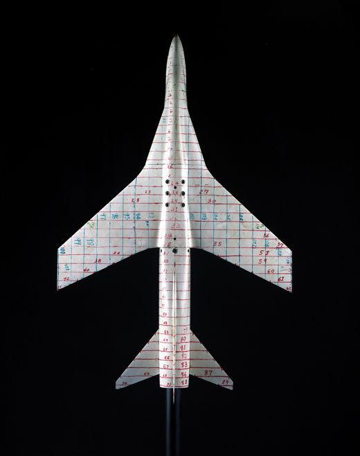
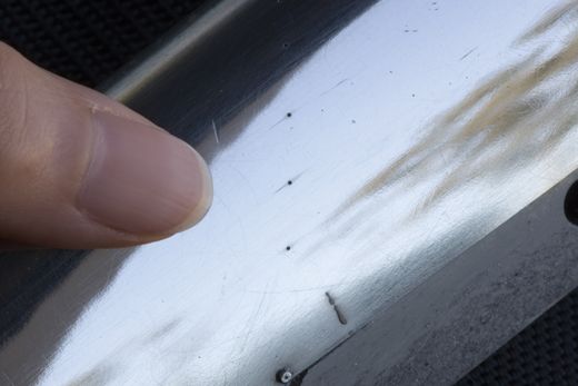
The basic results of most wind tunnel tests are “forces and moments”—the loads placed on the model by moving air. But investigators are interested in much more. To facilitate stress analysis and structural design, engineers drill minute holes, sometimes numbering in the thousands, in the skin of a model and connect them to pressure sensors. Another way to measure pressure involves a chameleon-like paint that changes color under pressure. To observe the paths taken by the air as it races past the model, tufts—which may be fluorescent filaments or just snippets of ordinary knitting yarn—are attached to the model like hair plugs. Alternatively, the model can be painted with a mixture of kerosene and a fine powder like talc or the china clay used for ceramics; the kerosene evaporates in the tunnel, leaving behind the tracks of the airflow like silt deposited by a flood. Slender streams of smoke help visualize flow paths, or, in some tests, the model is immersed in slowly flowing water and enmeshed in fine strands of fluorescent dye that glow under ultraviolet light like so many tropical fish (Boeing studied the landing flaps of the 747 this way). Special aeroelastic models, built to imitate the flexibility and mass distribution of the full-scale airplane, test susceptibility to destructive flutter. Even noise comes in for wind tunnel testing: A large model of the Boeing 777 was tested at Ames with highly directional microphones to locate the sources of aerodynamic noise; one major culprit turned out to be the tips of the landing flaps.
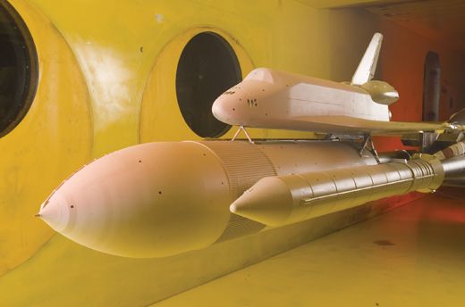
Though most wind tunnel models are eventually discarded, those of airplanes still in production or certain types of use are kept in storage, to be dusted off and re-tested when modifications are contemplated or problems arise in service. One of those is Ames’ three-percent model of the space shuttle. After the 2003 Columbia disaster heightened concern about the trajectories of falling foam and ice, the highly detailed model was re-tested to assess the effects of replacing a large slab of foam that covered wiring and hydraulic lines on the external propellant tank with small metal shields. Ames first subjected the changes to computational investigation, using its supercomputer, then tested them in the wind tunnel to confirm the results. The agreement, remarkably, was good, though the task—involving tumbling irregular shapes with turbulent and separated flows, and large differences in scale for different components—was, from a computational standpoint, extremely difficult. “This was a big win for CFD,” boasts NASA’s Stuart Rogers, an aerodynamicist and award-winning developer of computational aerodynamics software, who directed the analysis. “We’ve come a long way.”
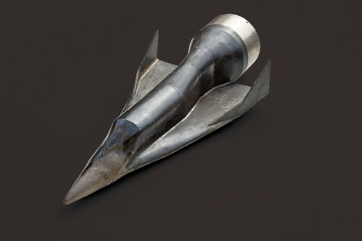
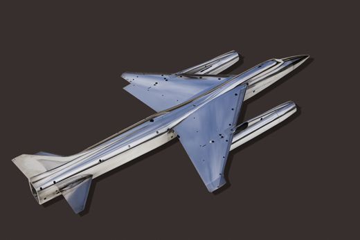
It’s ironic that at the same time numerical analysis challenges the primacy of the wind tunnel for aerodynamics research, the creation of wind tunnel models is becoming increasingly digital. The same computer-aided, design-generated digital definition of the airplane’s shape serves as a basis for both CFD and wind tunnel models. Specialist shops like Tri-Models—there are four or five independent ones in the United States, in addition to those operated by airframe manufacturers—employ numerically controlled milling machines that shave away at aluminum or stainless steel billets within closed cabinets while minders twiddle their thumbs. Completed models are then mounted on a measuring table and their contours checked at thousands of points with an electronic indicator. The hum of ventilation fans is interrupted only by faint bleeps of electronic satisfaction as the coordinates of each point are tucked away in a computer file.
At Ames, Kurtis Long, an irrepressibly good-natured specialist in the aerodynamics of surface ships, adjusts the alignment of a yard-long ship model in a wind tunnel test section. The purpose of the test is to map air disturbances in the wake of ships’ superstructures, because helicopters landing on their aft decks may fly through them.
Long’s model ship—delicately detailed, down to each railing, antenna, and hatch—came into being in Valencia, California. Valencia’s industrial parks contain several firms engaged in the futuristic business of stereolithography (SL), a way to manufacture single examples of complex objects by a completely robotic photochemical process.
SL creates solid objects of extreme complexity by selectively hardening an epoxy-like liquid with laser light. The process begins with a computer file, a cloud of numbers defining the shape of an object as a series of cross-sections at intervals of a few thousandths of an inch. Inside the SL machine, a simple metal cabinet with an angled window—think of it as a three-dimensional printer—an ultraviolet laser dances across the surface of several gallons of liquid photopolymer, a clear plastic liquid that hardens when the laser contacts it. A perforated floor immersed in the polymer drops by a few thousandths of an inch and the tremulous blue-violet light, directed by the computer file, sketches anew. Over and over and over—there is no sound, no one watches, no waste results. When the process, which advances at a rate of inches per hour, is finished, the perforated floor rises to the surface and the newborn object—a gear, a turbine, a wing, a ship, anything you like—emerges from the liquid like Aphrodite: perfect, virginal, and untouched by human hands.
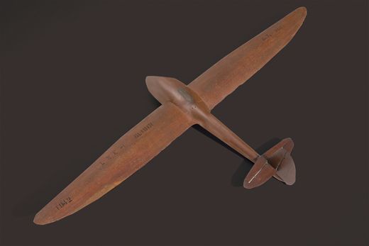
Stereolithography and numerically controlled machining represent the final stage in the withdrawal of the human touch from the making of wind tunnel models. The craftsmen who carved mahogany for Douglas and Northrop and Lockheed are mostly gone; likewise the sheet metal men who built up countless impeccable wing sections for NACA, and the artisans whose files and sanders sculpted massive steel to the precision of a clockwork. Their skill was impressive, and no doubt their satisfaction was great. But technology moves forward, toward pilotless airplanes built by pilotless machines, and the art and science of wind tunnel testing moves with it.