The Perfect Wind Storm
In the 1950s, engineers at Cleveland’s brand-new supersonic wind tunnel battled shock waves, unstarts, and the local power company.
/https://tf-cmsv2-smithsonianmag-media.s3.amazonaws.com/filer/The_Perfect_Wind_Storm_1_FLASH.jpg)
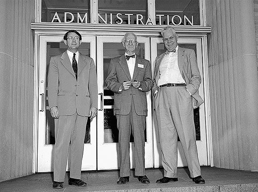
In May 1956, Cleveland was hit with record wind storms, and residents were still digging out of the debris when the Lewis Flight Propulsion Laboratory in nearby Berea, Ohio, debuted what was then the world’s most powerful wind tunnel (and one of the most powerful today). Edward Sharp, director of the propulsion arm of the National Advisory Committee for Aeronautics’ propulsion lab, introduced the 10 x 10, named for the dimensions of the tunnel’s test section.
The 10- by 10-foot supersonic wind tunnel was the preeminent achievement in a post-war response to the V-2 rockets and high-speed fighters Germany had fielded in World War II. The 1949 Unitary Plan Act had established supersonic wind tunnels for the NACA in Virginia, California, and now Ohio, as well as Air Force facilities in Tennessee. Congress wanted to ensure that the United States would never again lag in aeronautical technology.
Much of the press corps must have listened with only one ear while thinking up such headlines as “Big Wind Blows Good”—anything to play up the irony of a wind tunnel’s unveiling being preceded by a wind storm. Sharp acknowledged the storm’s power by securing his tie with two clips shaped like Century Series fighters.
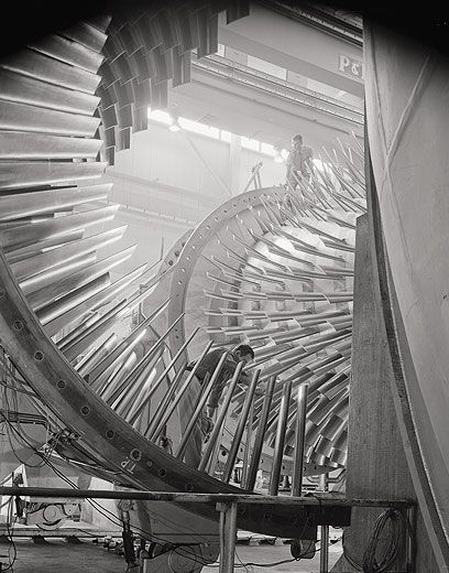
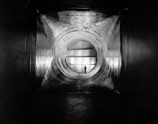
At the presentation, tunnel designer Harold Zager noted the stainless steel walls’ subtle curvature, designed to transition the flow from subsonic to supersonic speeds in an hourglass-shaped nozzle upstream of the test section. “I worked for the guy who designed the supersonic nozzle contours. We laid those out with the method of characteristics,” he says today, referring to a design procedure that enabled him to solve the complex equations governing supersonic flow using little more than a slide rule and a drafting board. “That makes the flow in the test section shock-free, if you do your homework right.”
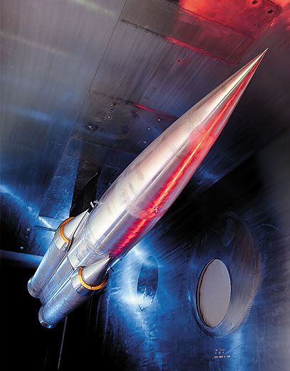
The goal for any tunnel designer is to create airflow in the test section that matches the conditions—airspeed, pressure, temperature—that an aircraft would encounter at a given altitude. This means no shock waves, no turbulence, nothing but smooth flow until the air reaches the model. The task is delicate enough with a subsonic wind tunnel, but with supersonic flow the stakes are much higher. The upstream nozzle must be precisely curved; the slightest deviation from the design can cause a fan of shock waves to emanate, dirtying the pristine flow of the test section and rendering the tunnel unusable.
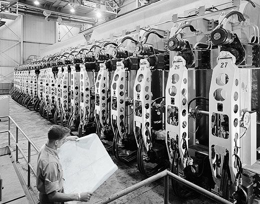
Zager also helped design the control room, where engineers could monitor both the model being tested as well as the terminal shock wave that is inevitable when running a supersonic tunnel. In the control room, camera monitors, pressure gauges, and a wall of alarms monitored the terminal shock—where supersonic flow terminates and subsonic flow begins—as it slowly progressed from the first nozzle down through the test section and past the model before settling near a second nozzle. If all went well, the shock wave would sit well behind the model, returning the wake of supersonic bomber models like the Convair B-58 and the Vought F8U to subsonic flow.
If things didn’t go well? The technical, if ungrammatical, term is “unstart.” When the tunnel unstarts, the shock wave shoots forward, striking the model from behind, and disappears through the first nozzle. According to Al Linne, an engineer at the tunnel today, “It’s the turbulence that really causes problems, because now you’ve got air that’s just going everywhere. Your model’s out there swinging around, doing things that visually, you wouldn’t believe.”
Because a supersonic wind tunnel consumes so much more power than a standard wind tunnel, the lab struck a deal with the Cleveland Electric Illuminating Company. If the tunnel engineers would request a weekly estimate of power, the power company would provide the electricity at a reduced rate, with two caveats: The tunnel would have to run only at night, and if the load on the grid was too high, the company could deny power.
“The toughest shift operation for me,” says retired test engineer Larry Smith, “was second shift, to make preparations for testing. That was back when my family was growing. You go to work at 10 at night and you come home at 9 the next morning. So you don’t see your family at all.”
But working at night had its perks. Says Bob Cubbison, one of the original research engineers at the 10 x 10, “The instrumentation guys used these kilns that would heat up and bond strain gauges to whatever it is they’d need to bond to. They found that a Magic Chef or a good Kenmore would work just as well as the industrial ovens. So they bought one of those, and you could have a hot cup of coffee at night, or the instrumentation guy would cook up a few hamburgs. The morning crew would come in and say: ‘What the heck went on here last night?’ ”
Because the power requirements were so high, the power company often had to pull strings. “Sometimes they’d get their power for us from a reservoir in Pennsylvania called Seneca,” Smith says. “Or from the Tennessee Valley Authority. One night, the whole facility just shut down, which is unheard of. That meant that all the power we were using had to be [absorbed by] the system. We heard later they had problems throwing circuit breakers all the way down to southern Tennessee. We went outside to find that it had stopped raining, but all these little copper BBs were scattered on the ground. Lightning had hit one of the transformers behind the tunnel and blew molten copper all over the place. Pretty wild. The power people didn’t appreciate that too much.”
Then there were the phone calls. “The telephone operator knew my name,” says Harold Zager. “People would complain about all kinds of things. Being a government agency, you have to follow up on all the complaints. We kept complete records of what we were doing. We could get complaints when we weren’t even running. One time, the kids were drag racing by the old tank plant there and they were blaming us for all the noise, the tire squealing. That took a while to find out.”
In 1958, a year after Sputnik was launched, the 10 x 10 came under the auspices of the nascent National Aeronautics and Space Administration. Abe Silverstein, who led the establishment, design, and construction of the tunnel, became director of the Lewis Research Center and championed using its resources to solve the Gemini and Apollo programs’ challenges.
After the Atlas-Centaur rocket experienced several launch failures, the program was brought to Lewis. Bob Cubbison and other engineers tackled the problems in the 10 x 10. A hydrogen vent plume on the Atlas, Cubbison says, would run down the length of the vehicle during launch, finding its way to small steering rockets near the base of the vehicle and causing an explosion. Cubbison and his fellow engineers used the tunnel to simulate the venting gas, with nitrogen instead of hydrogen, and found they could prevent the explosions simply by changing the angle at which the plume entered the airstream.
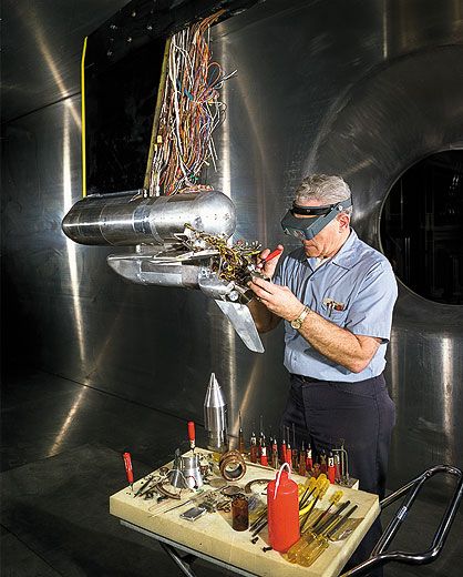
During the space shuttle program’s design phase, the 10 x 10 was ideal for engineers who wanted to test a scale model of the shuttle’s engines and solid rocket boosters. Ordinarily, the fumes exhausted during operation of a jet engine or a rocket motor would contaminate the recirculating air of a conventional wind tunnel. But the 10 x 10 could operate in two modes: open-loop and closed-loop. In open-loop, the tunnel draws air in from the atmosphere, passes it through the test section, and exhausts it without recirculation. The open-loop configuration enabled the 10 x 10 to accommodate live rocket motors and jet engines. “We ran a lot of base heating and instrumentation locations on the shuttle [scale] models,” says Zager. “When the rocket fires, you get a plume, and that conducts heat to the base of the vehicle. [At altitude, where the pressure is very low, a plume can widen and heat the rocket’s outer skin as well as instrumentation and hardware just above the nozzle. The thrust-vector hardware surrounding the space shuttle’s solid rocket booster nozzles is shielded by a 'thermal curtain' to protect against such heating.] Then you worry about where the plume goes at the different Mach numbers and densities. You have some problems with the model sometimes. Rocket blows up and messes up the test section. We never really had a serious accident though.”
In the 1980s, the tunnel returned to its original purpose, providing a platform for military and civilian supersonic aircraft such as the Lockheed YF-12, as well as concepts for the National Aerospace Plane, some of which were unnerving. “I recall the NASP guys talking about passengers riding on top of this huge liquid oxygen and liquid hydrogen tank,” says Larry Smith. “That was kind of crazy to even think about. We had an Air Force test come in once. They wanted to run a hydrogen/oxygen model, and the flow rates were horrendous. Seven pounds of oxygen a second and three and a half pounds of hydrogen. They wanted to do 30-second runs at different Mach numbers. They were going to bring in these huge tankers right next to the airport. They wanted to run hydrogen up to 1,000 degrees Fahrenheit, which is the temperature that it starts to self-detonate. The Air Force eventually pulled the plug though. I was thrilled because all that hydrogen and oxygen, it was a bit scary.”
While the tunnel was originally designed to provide speeds up to Mach 4, potential damage to the stainless steel blades of the two compressors limits the top speed to Mach 3.7. The new generation of engineers is pushing that restriction. “Ordinarily, we use a flexible wall to determine the Mach number,” says test engineer Christine Pastor. “Hydraulic jacks push the wall closer in just the right shape to prevent shock waves while we increase the speed. But you can only go so far before you risk an unstart.” So they trick it. Because supersonic flow actually gains speed around a corner (subsonic flow rounding a corner from a small area to a much larger one expands, losing speed), engineers like Pastor have devised a way to pass the tunnel air around a plate placed at an angle in front of the model. The flow hits the plate, accelerates around the angle, “and that's how you turn Mach 3.5 into Mach 4.5.”
In 1995, the 10 x 10 was named after the man who towered over nearly every one of its programs. Today, the Abe Silverstein Supersonic Wind Tunnel—the world’s largest propulsion SWT—runs much the same way it did 55 years ago. (In 1999, the Lewis Research Center was renamed the Glenn Research Center.) In the test section, cold war supersonic bombers have been replaced with parachutes from the Mars Science Laboratory mission, and Pastor wears F/A-18 earrings that look a lot like the Century Series tie clips Edward Sharp wore on opening day.
Aeronautical engineer and writer Jeremy Davis lives in Indianapolis.